1. Valve Overview
1.1 Product Definition and Application
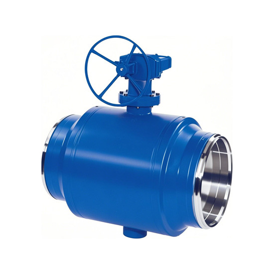
The eccentric hemispherical valve is a type of valve operated by rotating a hemispherical element via an eccentric crankshaft. Its core features include:
Eccentric Structural Design: The rotation center of the hemisphere (valve core) is offset from the center of the valve seat, ensuring no friction between the sealing surfaces during opening or closing. This significantly reduces wear and extends service life.
High-Efficiency Sealing Mechanism: When closing, the eccentric crankshaft gradually wedges the hemisphere into the valve seat, forming either a metal-to-metal hard seal or an elastic soft seal (depending on operating conditions). This is especially suitable for harsh media containing particles, fibers, or slurry.
Application Scenarios:
Industrial wastewater treatment, pulp and paper production, alumina transport, hydraulic slag removal in power plants, urban heating systems, mine slurry pipelines;
Suitable for cutting off or regulating two-phase flows (solid-liquid/gas-solid mixtures), high-velocity and highly abrasive fluids—where conventional ball valves may fail.
1.2 Model Code Interpretation
Example: Model Q347F
Q: Ball valve type;
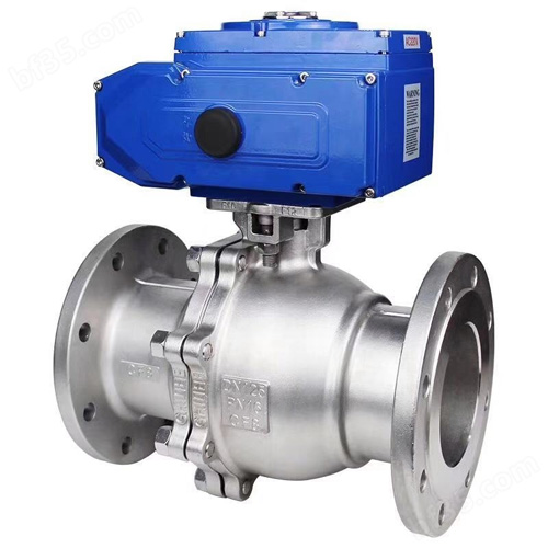
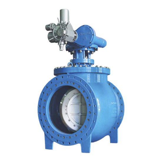
3: Actuation method (worm gear drive);
4: Connection type (flanged);
7: Structural form (eccentric hemispherical valve);
F: Sealing surface material (PTFE or fluoroplastic; optional metal seal such as type Y).
Type Distinction:
Top-entry: Eccentric shaft assembly is removed from the top of the valve body (maintenance without pipeline disassembly; suitable for buried or space-constrained installations);
Side-entry: Compact valve body with bidirectional flow design, ideal for piping systems with strict space requirements.
2. Main Technical Parameters
2.1 Pressure and Testing Standards
Nominal pressure (PN): PN10 (1.0MPa), PN16 (1.6MPa), PN25 (2.5MPa), PN40 (4.0MPa), Class 150~Class 2500 (ANSI);
Strength test pressure: 1.5× nominal pressure (≥15 minutes holding time, no deformation or leakage);
Sealing test pressure: 1.1× nominal pressure (≥15 minutes holding time, no leakage); special low-pressure sealing test (e.g., 0.6MPa for gas-solid mixtures).
2.2 Operating Conditions
Working Temperature:
PTFE seat: -29℃ ~ +180℃ (short-term ≤200℃);
Metal seal or modified materials (e.g., PEEK): -29℃ ~ +425℃ (for high-temperature steam or abrasive conditions);
Applicable Media: Water, sewage, steam, oil, natural gas, slurry, pulp, coal ash, alumina, weakly corrosive acids and alkalis, and other mixed fluids containing particles/fibers;
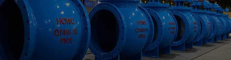
Body/Cover Materials: Cast steel (WCB), stainless steel (CF8/CF8M), ductile iron (QT450), sour service steel (NACE MR0175);
Eccentric Shaft/Hemisphere Materials: Hardened alloy steel (nitrided/chrome-plated), wear-resistant stainless steel (2Cr13/316), resistant to erosion and abrasion;
Seat Materials: PTFE, fluoroplastics, metal seals, or modified polymer materials depending on operating conditions.
Soft vs. Hard Sealing
Soft Seal: PTFE, reinforced PTFE (suitable for clean fluids and low-pressure systems);
Hard Seal: Alloy nitrided steel, tungsten carbide overlay, bimetallic sealing (wear-resistant and heat-resistant; suitable for high-abrasion or high-temperature conditions).
2.3 Structural Dimensions
Nominal diameters DN40~DN1600 correspond to flange dimensions (GB/T 9113 / ASME B16.5) or welded ends (ASME B16.25). Face-to-face dimensions comply with GB/T 12221 (straight-through type) or API 6D standards. Full bore design ensures the hemisphere channel diameter matches the pipeline, minimizing head loss.
3. Structure and Working Principle
3.1 Key Component Analysis
Valve Body & Cover: Integral casting or welded structure, mid-flange connection (O-ring / flexible graphite seal), top-entry allows maintenance without pipeline removal;
Eccentric Crankshaft Assembly: Shaft mounted via bearings in the valve body, one end connected to the hemisphere, the other driven by handwheel or worm gear;
Hemisphere (Valve Core): Solid or hollow hemisphere, coaxial with pipeline when open; sealing surface precision-ground or overlayed with wear-resistant alloy;
Valve Seat Assembly: Floating metal seat (axial/radial wear compensation), spring-loaded or pressure-assisted self-sealing (dual eccentric design for automatic centering);
Sealing System: Soft seal (PTFE, etc.) or hard seal (metal-to-metal), with fire-safe and anti-static features for gas applications.
3.2 Operating Mechanism
Opening: Counterclockwise rotation of the handwheel drives the eccentric crankshaft to rotate slightly, disengaging the hemisphere from the seat and retracting it into the valve cavity—allowing unobstructed flow (full bore);
Closing: Clockwise rotation of the handwheel pushes the hemisphere gradually into the seat; sealing surfaces only contact at the final moment, avoiding friction during the entire stroke;
Eccentric Wedge Sealing: The crankshaft’s eccentricity amplifies the wedging force, tightening the seal as the valve closes—compensating for wear and ensuring reliable bidirectional sealing, especially under pressure fluctuations.
Design Advantages:
Frictionless opening/closing eliminates long-term wear issues of traditional ball valve sealing surfaces;
Hemisphere retracts into the cavity, reducing direct media erosion and enabling self-cleaning flow paths to prevent debris accumulation.
4. Standards and Certifications
Design Standards: GB/T 12237 (Steel Ball Valves), API 6D (Oil & Gas Pipelines), ASME B16.34 (Pressure-Temperature Ratings);
Testing Standards: GB/T 13927 (General Pressure Testing), JB/T 9092 (Soft Seal Reliability), API 598 (Fire Testing);
Connection Standards: GB/T 12221 (Face-to-Face Dimensions), ASME B16.25 (Butt Weld Ends);
Special Certifications: API 607 / 6FA (Fire-Safe Design), ISO 15156 (Sour Service Compatibility), EN 1797-1 (Oxygen Media Suitability).
5. Selection Guidelines
1. Material Selection
Water / Steam / Oil: Carbon Steel (WCB) + PTFE Seat (Economical Option);
Sewage / Pulp / Particulates: Stainless Steel (CF8M) + Hardened Alloy Seat (Wear & Corrosion Resistant);
Gas / Cryogenic: Low-Temperature Steel (LCB) + Fire-Safe & Anti-Static Structure (Optional PEEK Seat).
2. Top-Entry vs Side-Entry
Top-Entry: Maintenance without pipeline disassembly, suitable for underground or frequent servicing scenarios;
Side-Entry: Compact structure with bidirectional sealing, ideal for space-constrained or high-pressure two-phase flow systems.
Soft Seal: PTFE, Reinforced PTFE (suitable for clean fluids and low-pressure systems);
Hard Seal: Alloy Nitrided Steel, Tungsten Carbide Overlay, Bimetallic Seal (wear and heat resistant, suitable for high-abrasion or high-temperature conditions).
3. Structural Dimensions
Nominal Diameter DN40~DN1600 corresponds to flange dimensions (GB/T 9113 / ASME B16.5) or weld ends (ASME B16.25). Face-to-face dimensions comply with GB/T 12221 (straight-through type) or API 6D standards. Full bore design (hemisphere channel diameter matches pipeline), resulting in near-zero head loss.
3. Structure and Working Principle
1. Key Component Analysis
Valve Body & Cover: Integral casting or welded structure, mid-flange connection (O-ring / flexible graphite seal), top-entry allows maintenance from above;
Eccentric Crankshaft Assembly: Shaft mounted via bearings in the valve body, one end connected to the hemisphere, the other driven by handwheel / worm gear;
Hemisphere (Valve Core): Solid or hollow hemisphere, coaxial with pipeline when open; sealing surface precision-ground or overlayed with wear-resistant alloy;
Valve Seat Assembly: Floating metal seat (axial/radial wear compensation), spring-loaded or pressure-assisted self-sealing (dual eccentric design for automatic centering);
Sealing System: Soft seal (PTFE, etc.) or hard seal (metal-to-metal), with fire-safe and anti-static design (for gas applications).
2. Operating Mechanism
Opening: Counterclockwise rotation of the handwheel drives the eccentric crankshaft to rotate slightly, disengaging the hemisphere from the seat and retracting it into the valve cavity—allowing unobstructed flow (full bore);
Closing: Clockwise rotation of the handwheel pushes the hemisphere gradually into the seat; sealing surfaces only contact at the final moment, avoiding friction during the entire stroke;
Eccentric Wedge Sealing: The crankshaft’s eccentricity amplifies the wedging force, tightening the seal as the valve closes—compensating for wear and ensuring reliable bidirectional sealing (especially under pressure fluctuations).
Design Advantages:
Frictionless opening/closing design solves the long-term wear issues of traditional ball valve sealing surfaces;
Hemisphere retracts into the cavity, reducing direct media erosion of the sealing surface, and the self-cleaning flow path prevents debris accumulation.
热门标签: