I. Product Overview
(1) Core Structural Design
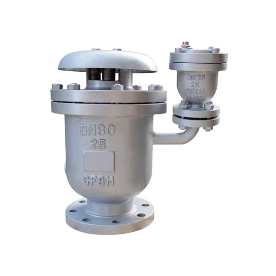
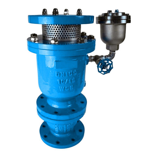
Composite Valve Body Assembly:
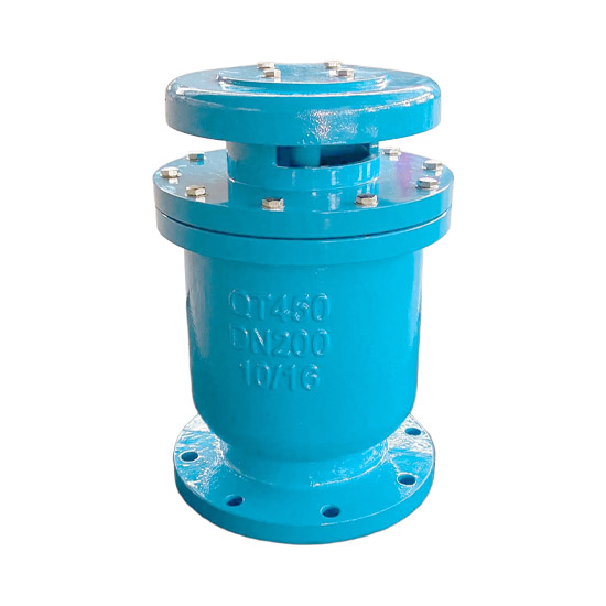
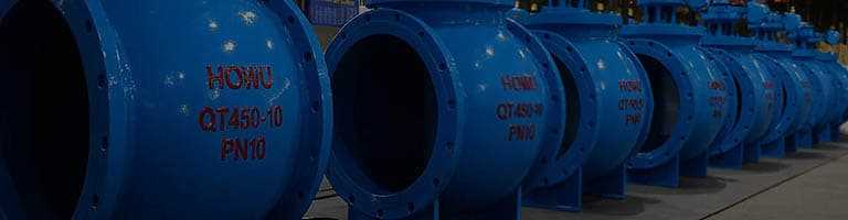
Valve body is cast from ductile iron (QT450-10) or stainless steel (304/316), offering vibration resistance and corrosion protection.
Ductile iron is suitable for standard water systems.
Stainless steel is ideal for seawater or chemical environments.
Flange sealing surfaces comply with GB/T 9115.1 (RF raised face) / GB/T 9115.2 (MFM male-female face):
Use RF for PN ≤ 1.6MPa
Use MFM for PN ≥ 2.5MPa
Diagonal bolt tightening prevents leakage.
Vertical installation design (valve cover facing upward), with tilt deviation ≤ 2°, ensuring precise movement of the float and buffer plate.
Buffer Valve System:
Buffer valve body: Pre-buffer structure positioned before the main exhaust valve inlet, with built-in guide shaft and buffer plate.
Buffer plate: Slides along the guide shaft, equipped with throttling holes (diameter 1.6–25mm).
Flow deflection protection: Prevents high-speed airflow from directly impacting the float assembly (patented protective sleeve or deflector disperses impact).
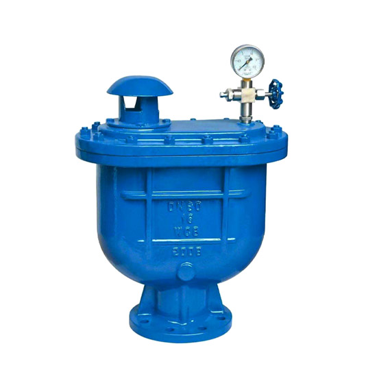
Dual-Mode Exhaust Mechanism:
Main exhaust port (large hole): Rapidly expels large volumes of air during initial water filling (flow speed can reach sonic level), reducing filling time.
Micro exhaust port: Continuously releases dissolved gases during normal operation, maintaining full-pipe conditions.
Dust protection mesh (mesh size 6–8mm): External mesh prevents debris from clogging the valve chamber.
Float Lever Sealing System:
Stainless steel float (density < water): Buoyancy drives valve disc to open/close exhaust ports.
Sealing ring made of NBR or EPDM rubber:
Hardness 60±5 Shore A (HG/T 2579)
Temperature resistance: -30°C to 100°C (use FKM for high-temperature steam)
Dual sealing protection (flange surface + valve disc seal).
(2) Core Operating Principle
Triple protection against water hammer via buffer valve throttling + float logic switching exhaust modes:
Pipe Filling Phase (Large Exhaust):
When empty pipe is filled, float sinks → main exhaust port fully opens → air rapidly expelled.
Once water fills the valve chamber, float rises to close the large port → stops bulk exhaust (activation pressure ≤ 0.02MPa).
Normal Operation Phase (Micro Exhaust):
Dissolved gases rise and accumulate at the top of the valve chamber → water level drops → float descends → micro port opens for exhaust → maintains full-pipe condition.
Pump Stop / Negative Pressure Phase (Buffering Against Rejoining Water Hammer):
Under negative pressure or flow interruption, float drops → main exhaust port opens for rapid air intake to balance pressure.
Buffer plate rises along guide shaft under positive airflow, partially blocking the main exhaust port (buffer valve throttling) → slows down air discharge → delays water column rejoining.
Air intake exits slowly through throttling holes, forming an air cushion to buffer pressure peaks (response ≤ 0.035MPa negative pressure), effectively eliminating rejoining water hammer.
II. Design and Manufacturing Standards
(1) Core Design Specifications
Basic Standards:
Complies with GB/T 35155-2017 “Anti-Cavitation Water Hammer Prevention Exhaust Valve” (equivalent to AWWA C512 / BS EN 1074-3), defining structure, performance, and testing methods.
Strength and pressure design based on GB/T 13927 “Industrial Valve Pressure Testing” (hydrostatic strength test at 1.5PN).
Flange connections follow GB/T 17241.6 (cast iron flange) / GB/T 9113 (steel flange); ASME B16.5 optional for international compatibility.
Key Parameter Design:
Air shut-off pressure: ≥ 0.1MPa (actual test > 0.4MPa for better performance)
Water shut-off pressure: ≤ 20kPa (ensures reliable float sealing under full-pipe conditions)
Buffer throttling hole diameter: 1.6–25mm, optimized for exhaust efficiency and water hammer suppression
Initial pressure drop: ≤ 0.05MPa (increased pressure drop due to debris buildup requires filter maintenance)
Material Selection Logic:
Standard water systems: Hot-dip galvanized ductile iron (zinc layer ≥ 85μm, economical and vibration-resistant)
Seawater / chemical / sanitary-grade: Stainless steel 304/316 with anti-corrosion lining (tensile strength ≥ 520MPa)
Cold regions: Anti-freeze sealing (-40°C to 80°C extended range)
(2) Manufacturing Process & Quality Control
Production Process Management:
Follows GB/T 19001 Quality Management System, covering casting, machining, non-destructive testing, and final inspection.
Body machining precision: GB/T 1804 grade m tolerance (linear dimensions without specific tolerance).
Key Process Standards:
Welding process (stainless steel models): Flange-to-body welding per GB 985.1 groove standard, radiographic inspection (JB/T 4730.2) Grade I qualified.
Surface treatment: Carbon steel hot-dip galvanizing (GB/T 13912) or epoxy coating ≥ 250μm on inner wall.
Float / buffer plate assembly calibration: Factory testing verifies large port exhaust, micro exhaust, negative pressure intake, and buffer throttling functions without jamming (≥ 3 cycle operations sampled).
Factory Inspection:
Hydrostatic strength test: 1.5× nominal pressure, 30 min hold (no leakage or deformation of shell)
Sealing performance verification:
Low pressure (0.02MPa) hold for 1 min, no leakage
High pressure (1.1PN) hold for 1 min, no seepage
Buffer function response test: Simulated negative pressure conditions confirm buffer plate throttling effect (rejoining water hammer pressure < 1.3× steady-state pressure)
热门标签: Rejoining Water Hammer Prevention Valve / Air Valve for Water Hammer Protection / Inlet Air Valve with Buffer Plug /