1. Product Overview
1.1 Core Structural Design
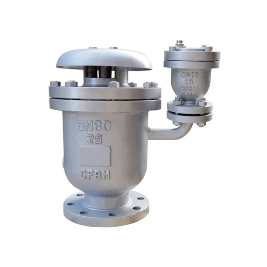
Valve Body Assembly:
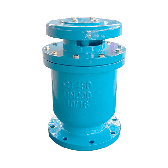
Manufactured from ductile iron (QT450-10) or stainless steel (304/316), offering vibration resistance and corrosion protection. Suitable for underground, vibrating, or corrosive environments. Material selection complies with GB/T 1348 and GB/T 1220.
Vertical installation design (valve cover facing upward), with an allowable deviation ≤2°, ensures precise float mechanism operation. For long-distance pipelines, installation is recommended every 500–1000 meters based on terrain slope.
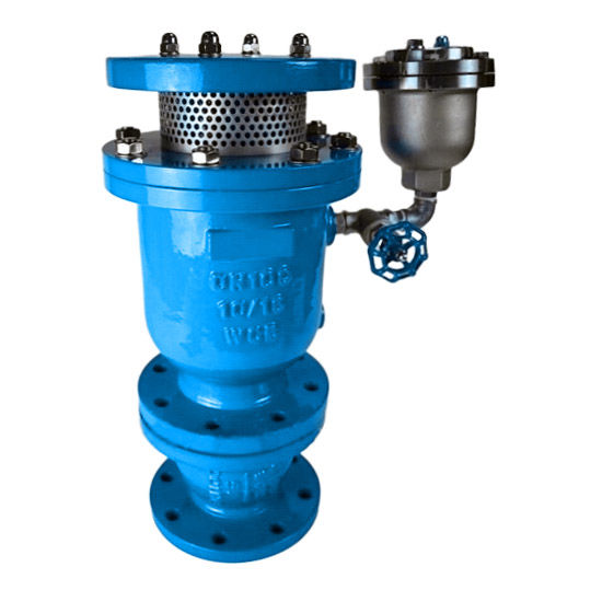
Float Control System:
Stainless steel float (density < water): buoyancy-driven actuation of valve disc to open and close large and small exhaust ports. Resistant to scouring and free from jamming.
Guide slot / buffer structure: prevents high-speed airflow from directly impacting the float, ensuring the float remains stable during filling and does not block the large port. (Patented deflector or protective sleeve design)
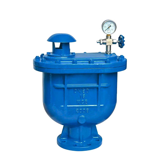
Dual Exhaust Port System:
Large exhaust port (diameter ≥25mm): rapidly discharges air during initial filling (flow speed may reach sonic level), significantly reducing filling time.
Small exhaust port (diameter 1.6–25mm): continuously releases dissolved gases during normal operation (micro-release mode), maintaining full-pipe flow.
Dust protection mesh (mesh size 6–8mm): prevents debris from entering the valve and causing functional failure.
Sealing System:
Sealing rings made of NBR or EPDM rubber: hardness 60±5 Shore A (compliant with HG/T 2579), temperature resistance from -30°C to 100°C. For high-temperature steam conditions, upgrade to FKM.
Flange sealing surfaces comply with GB/T 17241.6 and GB/T 9113 (RF raised face or MFM male-female face). Bolts tightened diagonally to prevent leakage.
1.2 Operating Principle
Pipeline Filling Phase (Bulk Air Discharge):
When filling an empty pipeline, the float rests at the bottom of the valve chamber due to its own weight. The large exhaust port fully opens, allowing high-speed air discharge (driven by Bernoulli effect).
Once the valve chamber is filled with water, the float rises due to buoyancy, closing the large port and stopping bulk air release. (Activation pressure threshold ≤0.02MPa)
Normal Operation Phase (Micro Air Release):
Small amounts of gas accumulate at the top of the valve chamber → water level drops → float descends → small port opens → gas is continuously discharged, maintaining full-pipe flow.
Pump Shutdown / Negative Pressure Phase (Rapid Air Intake):
During power failure or negative pressure, water flow stops or water level drops → float descends → large port opens rapidly → external air is drawn in to balance pressure, preventing pipe deformation, vibration, or rupture. (Negative pressure protection response ≤0.035MPa)
2. Design and Manufacturing Standards
2.1 Design Specifications
Basic Standards:
Strictly complies with CJ/T 217-2005 “Composite High-Speed Air Intake and Exhaust Valve for Water Supply Pipelines,” defining structure, performance, and testing methods.
Flange connections follow GB/T 17241.6 and ASME B16.5 (Class 150/300).
Strength design follows GB/T 13927 “Industrial Valve Pressure Testing,” with hydrostatic test pressure ≥1.5 times nominal pressure.
Key Parameter Design:
Air shut-off pressure: ≥0.1MPa (float lifted by airflow to close valve; actual test value >0.4MPa preferred).
Exhaust capacity: initial discharge through large port 10–50 m³/h (DN50–200); micro-release ensures stable removal of dissolved gases.
Pressure drop control: initial installation pressure drop ≤0.05MPa (may increase with debris accumulation; filter maintenance required).
Material Selection Logic:
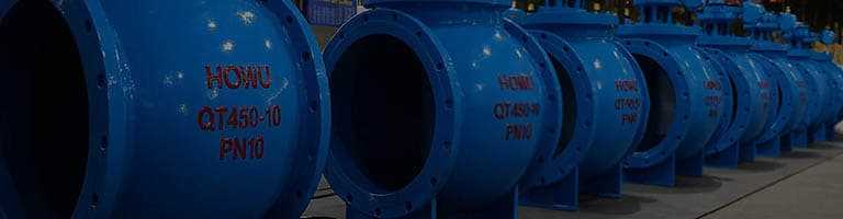
Standard water systems: hot-dip galvanized ductile iron (economical and vibration-resistant; zinc layer ≥85μm).
Seawater / chemical / sanitary-grade: stainless steel 304/316 with internal anti-corrosion lining (tensile strength ≥520MPa; GB/T 1220 compliant).
Cold regions: frost-resistant sealing (operating temperature range extended to -40°C ~ 80°C).
2.2 Manufacturing Process and Quality Control
Production Process Management:
Complies with GB/T 19001 Quality Management System, covering raw material inspection, casting/machining, non-destructive testing, and final factory inspection.
Body machining precision follows GB/T 1804 grade m tolerance (for unspecified linear dimensions).
Key Process Standards:
Welding process (stainless steel models): flange-to-body welding follows GB 985.1 groove standards; radiographic inspection per JB/T 4730.2, Grade I qualified.
Surface treatment: carbon steel parts hot-dip galvanized (GB/T 13912) or epoxy-coated (internal layer ≥250μm).
Float calibration testing: factory verification of large port exhaust, small port micro-release, and negative pressure intake without jamming (minimum 3 cycle tests).
Factory Inspection:
Hydrostatic strength test: 1.5× nominal pressure held for 30 minutes (no leakage or deformation; GB/T 13927 compliant).
Sealing performance verification:
Low pressure (0.02MPa) held for 1 minute without leakage.
High pressure (1.1× PN) held for 1 minute without penetration. (Dual-pressure validation)
Air shut-off / water seal pressure test: confirms float response to differential pressure threshold (0.1MPa shut-off pressure compliance).
Популярные теги: Air Release Valve /