I. Valve Overview
1. Product Definition and Application
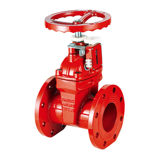
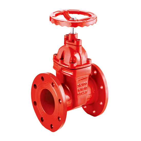
The national standard metal-sealed gate valve is a shut-off valve featuring a metal-to-metal sealing structure. It controls the flow of media by vertically raising or lowering the gate along the stem. Key features include:
• Metal-to-Metal Hard Sealing Design: The sealing surfaces of the gate and seat are made of hard alloys (such as Stellite cobalt-based alloy, tungsten carbide) or high-strength stainless steel (e.g., 13CrSTL, 304/316 overlay). When closed, sealing is achieved through medium pressure or external force-driven wedge action, ensuring zero leakage under high temperature, high pressure, and severe wear conditions.
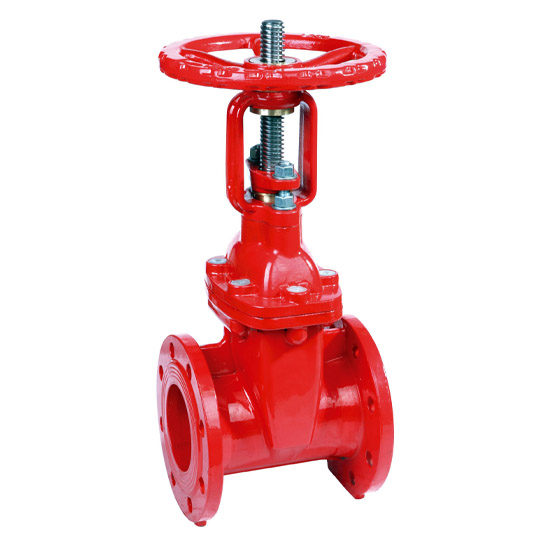
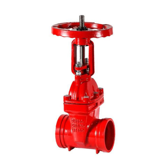
• Rising Stem Drive System: The stem is rigidly connected to the gate and fully exposed during operation (trapezoidal thread drive). The gate is driven linearly by a handwheel or actuator, and the stem height clearly indicates the valve’s open/closed position (fully open → stem at top; fully closed → stem at bottom).
• Wedge-Type Gate Structure: Typically includes elastic single wedge gates (for small and medium diameters) or rigid double wedge gates (with automatic wear compensation). The wedge angle compensates for thermal deformation or installation deviation, and the valve supports bidirectional flow without directional restrictions.
• Flat-Bottom Seat Flow Path: Full bore design with near-zero flow resistance. Suitable for high-temperature, high-pressure, particle-laden, or corrosive media systems in petroleum, chemical, power, metallurgy, and heating industries (e.g., steam, oil, natural gas, acid/alkaline solutions).
2. Model Code Interpretation
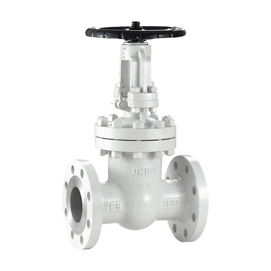
Example: Z41H-16C
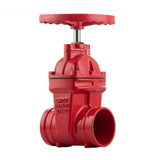
• Z: Gate valve type • 4: Connection type (flanged; alternatives: welded – Z61H, threaded – Z11H) • 1: Structure type (elastic single wedge gate; double gate – Z42H) • H: Sealing surface material (metal hard seal; alternatives: X – rubber soft seal, Y – hard alloy) • 16: Nominal pressure (PN16, 1.6 MPa) • C: Body material (cast steel WCB; alternatives: P – stainless steel CF8, R – 316L, Q – ductile iron)
Other common models: • Z41Y: Hard alloy sealing surface (enhanced wear resistance) • Z941H: Electric actuated type • Z641H: Pneumatic actuated type • Z40H: Socket weld end (requires matching flange)
II. Main Technical Parameters
1. Pressure Ratings and Test Standards
• Nominal Pressure (PN): PN10 (1.0 MPa), PN16 (1.6 MPa), PN25 (2.5 MPa), PN40 (4.0 MPa), PN64 (6.4 MPa), PN100 (10.0 MPa)
• Strength Test Pressure: 1.5×PN (≥15 min pressure holding without deformation or leakage; e.g., PN16 = 2.4 MPa hydrostatic)
• Sealing Test Pressure: 1.1×PN (≥15 min bidirectional pressure holding without leakage; e.g., PN16 = 1.8 MPa air/water)
• Test Standards: Strictly comply with GB/T 13927 (general valve pressure test), API 598, or JB/T 9092 to ensure long-term sealing and structural integrity
2. Applicable Operating Conditions
• Operating Temperature: – Standard stainless steel overlay: -29℃ ~ +425℃ (ideal for steam / thermal oil systems) – Hard alloy sealing surface (Stellite): -29℃ ~ +550℃ (for high-temperature furnaces / cracking units) – Special customized liners: up to +650℃ (requires sulfur-resistant / high-temperature design)
• Applicable Media: – Water (including particle-laden wastewater) – Steam (superheated / saturated) – Oil (crude / heavy) – Natural gas – Diluted acid and alkaline solutions – Urea solution – Sour gas (requires NACE certification)
• Body Materials: – Cast steel (WCB, economical) – Stainless steel (CF8 / CF8M, corrosion-resistant) – Chrome-moly alloy steel (WC6 / WC9, high-temperature and pressure resistant) – Low-temperature steel (LCB / LCC, cryogenic resistant)
• Gate / Seat Sealing Surface: – Basic: Stainless steel overlay (12Cr13, HRC38–42) – Enhanced: Stellite alloy (Stellite 6, HRC45–50, erosion-resistant)
• Stem Material: – Stainless steel (2Cr13, quenched and nitrided, anti-scuffing and corrosion-resistant) – Chrome-moly steel (for high-temperature service)
• Packing Seal: – Braided flexible graphite (for high-temperature, high-pressure steam) – Reinforced PTFE (high chemical compatibility)
3. Structural Dimensions
• Nominal Diameter: DN15~DN1200 (larger sizes customizable) • Flange dimensions and face-to-face length (L) strictly match GB/T 12221 (straight-through type), GB/T 9113 (steel flanges), or JB/T 79 (cast iron flanges) • Full bore flow path with near-zero flow resistance coefficient
III. Structure and Operating Principle
1. Metal Hard Sealing Mechanism
• Sealing Surface Pairing: Gate and seat use materials with differential hardness (seat slightly harder), e.g., Stellite alloy overlay seat + hardened steel gate, reducing scuffing risk
• Self-Sealing and Forced Sealing: – Self-Sealing: High-pressure medium pushes the gate tightly against the downstream seat (medium-assisted sealing, ideal for outlet side) – Forced Sealing: External torque (handwheel / actuator) wedges the gate into the seat, ensuring reliable sealing under low pressure or bidirectional flow
• Elastic Compensation Advantage: Elastic wedge gate includes a central deformation allowance (~0.1 mm) to adapt to thermal expansion/contraction or installation deviation, extending sealing life
2. Rising Stem Drive System
• Visual Opening Indication: Exposed stem length directly reflects gate position (fully closed → stem retracted; fully open → stem extended)
• Trapezoidal Thread Drive: Handwheel rotation converted to linear stem motion via nut; efficient and low-torque (worm gear mechanism optional for DN ≥300 valves)
• Triple Sealing Protection: Stem packing chamber includes braided flexible graphite + metal bellows ring (high-temperature, high-pressure leak prevention), significantly reducing friction during operation
3. Operating Mechanism
• Opening: Counterclockwise rotation of handwheel raises stem, gate lifts off seat, flow path fully opens (flow resistance coefficient ≈0.1)
• Closing: Clockwise rotation lowers gate to seat, wedge surface forced into position + medium pressure self-tightening (optimized for unidirectional sealing), ensuring zero-leakage shut-off
• Limit Protection: Fully open position corresponds to stem at top (prevents over-travel and thread damage). For long-term operation, reverse 1/4–1/2 turn to compensate for thermal expansion and prevent stem lock-up
IV. Main Technical Standards and Certifications
• Design Standards: – GB/T 12234 (Steel Gate Valves) – API 600 – API 6D (Pipeline Gate Valves for Petroleum Industry)
• Test Standards: – GB/T 13927 – AWWA C509 (reference for resilient seated valves; enhanced strength testing for metal seals) – BS 6755 (fire-safe compliance)
• Connection Standards: – GB/T 17241.6 (Cast Iron Flanges) – GB/T 9113 (Steel Flanges)
• Special Certifications: – NACE MR0175 (Resistance to Sulfide Stress Cracking) – ATEX (Explosion Protection for Hazardous Environments) – CRN (Canadian Pressure Vessel Registration)
热门标签: Gate Valve /