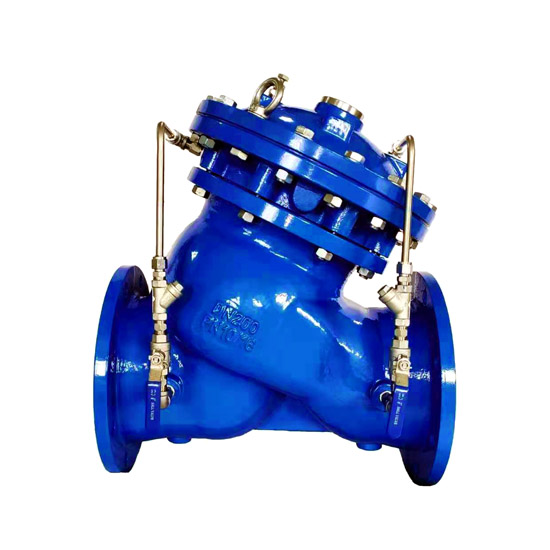
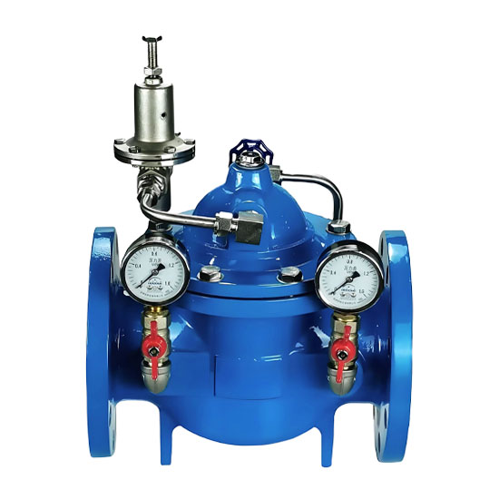
The Multi-Functional Pump Control Valve is an intelligent hydraulic control valve specially designed for pump outlet pipelines. It is installed between the pump outlet and the main pipeline. Its core functions include:
Preventing medium backflow: Avoids reverse water flow impacting the impeller when the pump is shut down, protecting the pump and motor from damage.
Eliminating water hammer hazards: Through a staged operation mechanism of "slow opening → quick closing → slow closing", the peak water hammer pressure is controlled within ≤1.3 times the working pressure (the water hammer pressure of traditional check valves can reach 3~5 times).
Integrated control replacing multi-valve combination: Replaces the combination of independent check valves, electric gate valves, and water hammer eliminators, saving space and reducing energy consumption and maintenance costs.
Fully automatic operation without electronic control: No external power supply or complex control system is required. The valve is driven by pressure changes in the pipeline when the pump starts or stops, achieving full interlocking synchronization with pump operations.
Typical application scenarios: High-rise building water supply systems, municipal pump stations, industrial circulating water systems, water conservancy hub pump stations, fire water supply pipelines, etc.
Efficient and reliable water hammer protection: The slow-closing time (adjustable from 3 to 120 seconds) is accurately matched to system operating conditions, significantly reducing the risk of pipeline vibration, noise, and pipe bursting.
Hydraulic drive for energy conservation and environmental protection: Uses the pressure of the medium itself as the power source, with no energy consumption. The valve body adopts a full-channel streamlined straight-flow design, resulting in low head loss (pressure loss coefficient ≤0.01MPa).
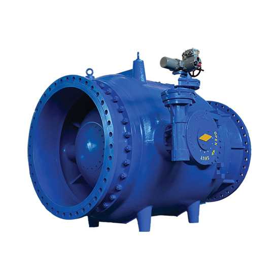
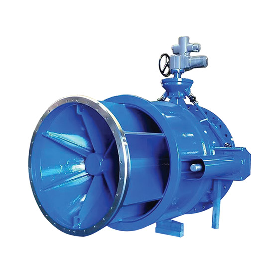
Compact structure with strong adaptability: Can be installed horizontally or vertically, and is suitable for various media such as clean water, sewage, and seawater (temperature range: 0~80℃). Specifications from DN50 to DN1400 cover different flow requirements.
Simple commissioning and maintenance: No professional electronic control commissioning is needed; the opening and closing speed can be calibrated by adjusting the pilot valve opening. The diaphragm/piston-type dual control chamber structure is easy to overhaul, enabling convenient online maintenance.
The valve is mainly composed of a main valve, dual control chambers (diaphragm-type / piston-type), a pilot valve system, and a connecting pipe assembly:
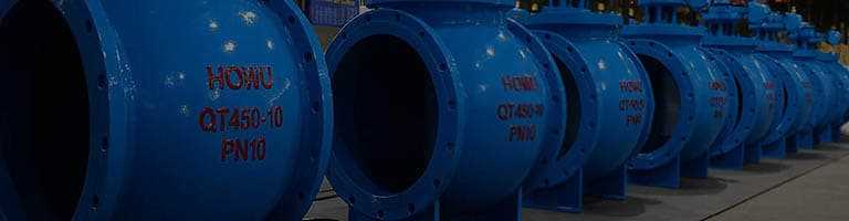
Valve body: Made of ductile iron (QT450), carbon steel (WCB), or stainless steel (CF8/CF8M). The straight-flow channel design reduces resistance.
Main valve disc assembly:
Valve seat: Hardened stainless steel or copper alloy sealing surface, resistant to scouring and wear.
Valve stem: Stainless steel material, with precise sliding guidance.
Slow-closing valve plate: Assists the main valve disc in staged closing to enhance water hammer buffering effect.
Dual control chamber drive mechanism:
Upper control chamber: Connected to the downstream of the pipeline (pump outlet end), with pressure relief speed controlled by the pilot valve (regulating valve A).
Lower control chamber: Connected to the upstream of the pipeline (main pipeline side) or the return pipeline. The diaphragm/piston transmits medium pressure to drive the main valve action.
External connecting pipe system: Includes small ball valves, filters, and micro-check valves, which are used for pressure charging/discharging adjustment of the control chamber and impurity filtration.
Flow guiding and protection components: An optional inlet Y-type filter prevents foreign objects from jamming the valve disc; an air release valve discharges air in the control chamber.
When the pump starts, the pressure in the pipeline rises.
The medium pressure pushes the diaphragm/piston of the lower control chamber upward, and at the same time, pressure enters the lower chamber through the inlet-side connecting pipe.
The pressure in the upper control chamber is slowly released to the outlet end through pilot valve B. The pressure in the lower chamber overcomes the residual pressure in the upper chamber and the spring force, pushing the main valve disc to open slowly and at a constant speed (opening time adjustable to 10~60 seconds), avoiding start-up water hammer caused by instantaneous water flow impact.
When the pump is powered off, the pressure in the pipeline drops sharply. The main valve disc quickly closes 90% of its stroke under the action of its own weight and spring force (quick closing stage, blocking most backflow to prevent pump reversal).
At the remaining approximately 10% opening, the medium at the outlet end is slowly filled into the upper control chamber through pilot valve A. The pressure in the upper chamber increases, and together with the residual pressure in the lower chamber, it causes the main valve disc to slowly close the remaining stroke (slow closing stage, extending the closing time to an adjustable 3~120 seconds), limiting the peak water hammer pressure to a safe range.
The micro-check valve ensures one-way flow of water in the control chamber, maintaining the stability of the slow-closing action.
Key control logic: By adjusting the opening ratio of pilot valves A and B, the quick-closing response speed and slow-closing time can be accurately calibrated to adapt to the system characteristics of different pipe diameters, lifts, and flows.
Valve body / Valve bonnet: Cast iron (gray cast iron HT250 / ductile iron QT450) for conventional systems; stainless steel (CF8/CF8M) for corrosive environments.
Valve disc sealing surface:
Soft seal: Nitrile rubber (NBR) or fabric-reinforced nitrile diaphragm (suitable for clean water systems, achieving zero leakage at ANSI Class VI level).
Hard seal: Stainless steel overlay welding or metal seal (suitable for media containing particles, enabling two-way high-pressure sealing).
Connection method: Mainly flange connection (RF face, conforming to GB/T 9113/ANSI B16.5 standards). For large-diameter valves (DN≥600), independent support is recommended.
Diaphragm-type: High control accuracy, suitable for small and medium diameters (DN≤600) and systems with strict sealing requirements.
Piston-type: Strong driving force, suitable for large diameters (DN>600), high-pressure, or high-flow rate working conditions, with better durability.
Популярные теги:
Water Control Valves /