I. Product Overview
1. Definition and Core Functions
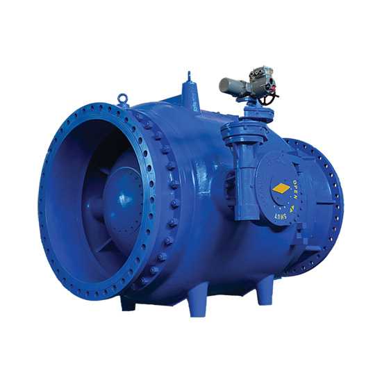
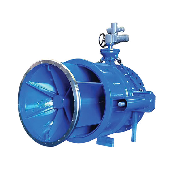
A fixed cone valve is a multifunctional control valve that regulates annular flow area by axially moving an external sleeve along a fixed cone body. It enables precise flow control, stable pressure regulation, and efficient energy dissipation. Its unique design addresses common issues in traditional valves under high head, large flow, and cavitation-prone conditions—such as vibration, wear, and poor control accuracy. Key advantages include:
Linear Flow Regulation: Sleeve opening is strictly proportional to flow rate (deviation ≤ ±3%), ideal for reservoir level control, hydropower bypass discharge, and long-distance pressure-reducing pipelines.
Superior Energy Dissipation and Anti-Cavitation: Flow expands around the cone to form a hollow jet (optionally constrained by a diffuser hood). Air entrainment and internal guide vanes concentrate cavitation bubbles at the flow center, preventing impact on valve body and downstream pipe walls.
Low Head Loss and Energy Efficiency: When fully open, the flow path is nearly straight-through, with a resistance coefficient of only 0.1–0.2 (compared to gate valves at ~0.8–1.5), significantly reducing energy consumption.
Compact Structure and Long Service Life: External drive components and a fixed cone with no moving parts reduce wear points. Metal-to-metal (Stellite/stainless steel) or composite (soft + hard) seals achieve bidirectional zero leakage (ANSI Class VI).
Easy Installation and Maintenance: Can be installed horizontally or at any angle. Sleeve guide lubrication and seal replacement can be performed online without draining the pipeline.
Typical Applications:
Water Resources & Hydropower: Dam flood discharge control, turbine bypass valves, surge tank level balancing.
Municipal Water Supply & Drainage: Reservoir emptying, pressure reduction in long-distance pipelines, irrigation flow distribution.
Industrial Systems: Metallurgical slurry discharge, gas/liquid flow regulation in wastewater treatment, energy dissipation in chemical two-phase flow pipelines.
II. Core Structure and Working Principle
1. Detailed Construction
The fixed cone valve consists of the following components:
Fixed Cone Assembly: Inverted conical structure (typically stainless steel or wear-resistant alloy), fixed at the upstream end of the valve body via guide vanes to evenly diffuse flow.
Sleeve Gate Disc: Stainless steel sleeve slides axially along the cone, driven by crank linkage or electric/hydraulic actuators. Fully open covers the cone; fully closed seals against the valve seat.
Dual Sealing System:
Primary Seal (Cone to Sleeve): Metal hard seal (Nitronic 60 alloy or Stellite overlay) for zero leakage under high pressure, or soft seal (EPDM/NBR rubber) for clean media.
Secondary Seal (Sleeve to Valve Body): O-rings or lip seals prevent external leakage.
Flow Guidance and Support:
Internal guide vanes (4–6 pieces) evenly split flow to eliminate vortex-induced vibration.
External guide rails (bronze alloy or self-lubricating materials) ensure smooth sleeve movement.
Energy Dissipation / Discharge Structure: Outlet may include a diffuser hood (to limit expansion angle) or direct atmospheric discharge for efficient energy dissipation.
2. Operating Mechanism
Flow Control: Actuator moves sleeve away from cone, increasing annular gap and linearly increasing flow (flow coefficient ≈ 0.75–0.86). Reverse movement reduces flow until shutoff.
Pressure Regulation: Based on constant flow or downstream pressure settings, sleeve automatically adjusts to balance system pressure fluctuations and prevent water hammer.
Energy Dissipation Principles:
Flow expands around cone forming a trumpet-shaped hollow jet; air friction atomizes and dissipates kinetic energy.
With diffuser hood, flow collides through nozzles, converting kinetic energy into pressure energy and canceling out forces—reducing downstream erosion.
Guide vanes split flow, suppress vortex vibration, and extend valve life.
III. Technical Specifications and Performance Indicators
1. Basic Specification Range
| Item | Parameter Range |
|---|---|
| Nominal Diameter (DN) | DN100–DN3600 (customizable to DN4000+) |
| Nominal Pressure (PN) | PN6–PN100 (Class 150–600LB) |
| Operating Temperature | -29℃ to 150℃ (soft seal ≤120℃; hard seal -29℃ to 425℃) |
| Flow Regulation Range | 0–100% linear adjustment, deviation ≤ ±3% |
| Leakage Class | Soft seal: ANSI Class VI (zero leakage); Hard seal: ≤0.1×DN mm³/s (FCI 70-2 Class IV) |
| Head Loss Coefficient | ≤0.2 (near straight-through flow) |
| Cavitation Protection | Bubble confinement via flow design, σ critical safety factor ≥0.4 |
| Operating Torque | Only 1/3–1/5 of equivalent gate valve; supports manual (worm gear), electric (explosion-proof), hydraulic drive |
2. Materials and Seal Grades
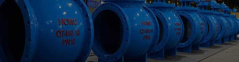
Valve Body / Cone: Carbon steel (Q345B), ductile iron (QT450-10), cast steel (WCB/WCC), stainless steel (CF8/CF8M), or chrome-moly steel (WC6).
Sleeve / Valve Seat: Hardened stainless steel (304/316L + Stellite overlay) or wear-resistant alloy (Nitronic 60).
Soft Seal Materials: Reinforced EPDM/NBR rubber (temperature range -29℃ to 150℃, lifespan ≥10 years).
Connection Types: Flanged (RF/RTJ face, GB/T 9113 / ANSI B16.5), butt-welded (GB/T 12224), or custom interfaces.
3. Actuator Compatibility
Drive Types: Manual (handwheel / worm gearbox), electric (integrated explosion-proof, ATEX certified), pneumatic (piston / diaphragm), hydraulic (hydraulic station).
Control Functions: Opening feedback signal (4–20mA analog or Modbus), PLC linkage, power-off hold, or ESD emergency shutoff.
Diffuser Hood Options: Choose standard diffuser (free discharge) or constrained diffuser (reduced impact zone) based on energy dissipation needs.
Популярные теги: Hydraulic Control Valve /