I. Product Overview
1. Definition and Functions
A Pressure Reducing and Sustaining Valve is an intelligent control device installed in pipeline systems. It automatically adjusts the valve opening to reduce the high-pressure medium upstream to the required stable pressure downstream. Its core functions include:
Pressure Control: Reduces excessively high pressure upstream (e.g., overpressure in municipal pipe networks, high-zone water supply pressure in high-rise buildings) to the safe operating pressure range of downstream equipment (e.g., water heaters, fire hydrants, irrigation sprinklers) (typical outlet pressure: 0.1~1.6 MPa);
Dynamic Pressure Sustaining: Regardless of changes in inlet pressure or flow rate, it automatically adjusts the opening to maintain constant outlet pressure (deviation ≤ ±5%~10% of the set value), avoiding equipment damage caused by pressure fluctuations;
Water Hammer Protection: Absorbs water hammer energy generated by sudden changes in water flow velocity through slow opening and closing characteristics (adjustable opening time: 5~60 seconds; adjustable slow closing time: 3~120 seconds), preventing pipeline vibration, noise, and pipe bursting;
Energy Conservation and Consumption Reduction: Eliminates redundant pressure in the system, reduces pump energy consumption, and extends the service life of downstream water-using appliances (e.g., water-saving faucets, water meters).
Typical Application Scenarios:
Building Water Supply: Zoned pressure reduction in high-rise buildings (addressing excessive water pressure on lower floors and insufficient water supply on top floors);
Municipal Systems: Pressure regulation in water plant transmission pipe networks, protection of secondary pressure boosting pump stations;
Fire Protection Systems: Pressure reduction and sustaining in fire hydrant pipe networks to ensure compliant terminal pressure (0.35~0.5 MPa);
Industrial Pipes: Boiler condensate recovery, hydraulic system pressure matching, pressure reduction control for chemical fluids;
Agricultural Irrigation: Pressure adaptation for drip irrigation/spray irrigation systems, avoiding poor atomization under low pressure or sprinkler damage under high pressure.
2. Technical Advantages
Self-Powered Operation Without Electronic Control: No external energy source or complex control system is required; it is fully driven by the pressure of the medium itself (minimum operating pressure ≥ 0.07 MPa);
Sensitive and Efficient Response: The diaphragm/piston-type dual control chamber structure enables millisecond-level response to pressure changes, with stable flow characteristics (pressure loss coefficient ≤ 0.01 MPa);
Integrated Design: Integrates pressure reduction, pressure sustaining, check, and water hammer elimination functions in one unit, replacing multi-valve combinations (check valve + electric valve + water hammer eliminator) to save space and costs;
Easy Installation and Maintenance: Supports horizontal or vertical installation with the valve bonnet facing upward; seals (diaphragm/piston components) can be replaced online, and long-term stable operation is achievable with regular filter cleaning;
Strong Material and Working Condition Adaptability: Valve bodies made of ductile iron, stainless steel, or copper alloy are suitable for clean water, sewage, seawater, and corrosive media; hard seals or soft seals (NBR/EPDM) meet different sealing requirements.
II. Core Structure and Working Principle
1. Detailed Explanation of Typical Structure
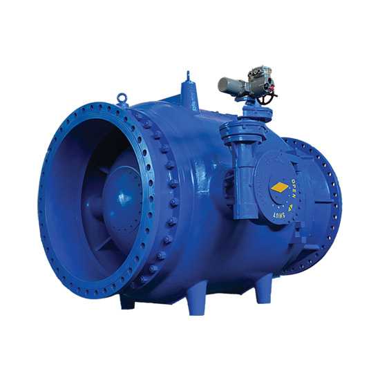
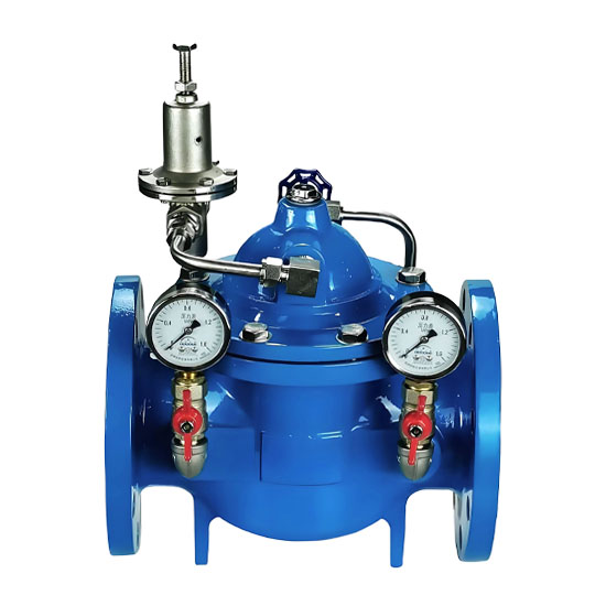
A Pressure Reducing and Sustaining Valve mainly consists of a main valve, a pilot valve, a control piping system, and a diaphragm/piston drive mechanism:
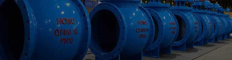
Valve Body Assembly: Features a straight-through full-channel design (made of ductile iron QT450, carbon steel WCB, or stainless steel CF8/CF8M), including an inlet port (high-pressure side), an outlet port (low-pressure side), and a valve chamber;
Valve Disc Sealing System:
Main Valve Disc: Made of hardened stainless steel or composite seal (rubber + metal) material, with its opening controlled by linking to the diaphragm/piston via the valve stem;
Valve Seat: Wear-resistant sealing surface (Stellite alloy overlay welding or nitrile rubber) ensures zero leakage;
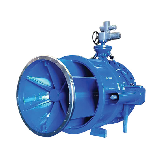
Drive Control Mechanism:
Diaphragm-Type (for small and medium diameters DN ≤ 600): An elastic fabric-reinforced nitrile rubber diaphragm senses the outlet pressure and pushes the valve stem to adjust the opening;
Piston-Type (for large diameters DN > 600 or high-pressure conditions): A metal piston transmits pressure difference-driven force, with a wear-resistant O-ring seal;
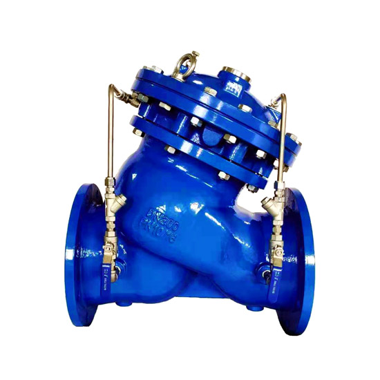
Pilot Valve and Piping System:
Pilot Valve: A brass or stainless steel needle valve that sets the target outlet pressure by adjusting the spring preload;
Control Piping: Includes copper ball valves (for isolation/commissioning), micro-filters (precision ≥ 50μm, preventing jamming by impurities), and pressure feedback pipes (connecting the outlet end to the upper chamber of the diaphragm/piston);
Flow Guiding and Protection Components: An optional Y-type pre-filter (installed upstream) prevents welding slag/particles from damaging the sealing surface; an outlet diffuser reduces air supply noise (suitable for vacuum air supply scenarios).
2. Analysis of Working Mechanism
The Pressure Reducing and Sustaining Valve achieves automatic adjustment based on the pressure balance principle and hydraulic feedback control:
Pressure Signal Collection: The outlet pressure is transmitted to the bottom of the pilot valve diaphragm via a pipe and compared with the adjusted spring preload;
Pilot Valve Action:
When the outlet pressure > set value: The pilot valve closes, the pressure in the main valve control chamber (upper chamber of the diaphragm/piston) increases, pushing the valve disc to reduce the opening, thereby decreasing the flow rate and lowering the outlet pressure;
When the outlet pressure < set value: The pilot valve opens for drainage, the control chamber pressure decreases, and the pressure before the valve pushes the valve disc to increase the opening, thereby increasing the flow rate and raising the outlet pressure;
Dynamic Stability Cycle: The main valve opening is continuously fine-tuned until the outlet pressure balances with the pilot valve spring force, achieving stable pressure reduction and sustaining;
Water Hammer Protection Mechanism:
When the pump starts: The control pipe is slowly pressurized, and the main valve opens slowly (avoiding start-up water hammer);
When the pump stops: The main valve disc quickly closes 90% of the stroke under its own weight and spring force to block backflow, while the remaining 10% opening is slowly closed through the control chamber (extending the closing time to buffer the impact of pump shutdown water hammer).
III. Technical Standards
Complied Specifications
Domestic Standards:
CJ/T 256-2016 "Split Pilot-Type Pressure Reducing and Sustaining Valves" (basis for design and manufacturing);
GB/T 13927 "Pressure Testing of General Valves";
GB/T 17241 Flange Standards;
International References:
ISO 5208 Pressure Testing;
ANSI B16.34 Valve Body Strength Requirements.
Hot Tags: